Monday, 30 December 2013

OSPF

           Open Shortest Path First           

1) Introduction-

-Allow routers to dynamically learn routes from other routers and to advertise routes to other routers.
-Keep track of the state of all network connection or links between itself and a network. 
-Link-State routing protocol.
-Most widely used 'Interior Gateway Protocol(IGP)'
-Operate within a single Autonomous System (AS).
-Transport IP, protocol type-89.
-Uses a Link-State routing algo. or shortest path first algo.
-Computes shortest path route using a method based on Dijkstra's  algo.
-Support VLSM/ Classless.

OSPF - Metric-

- Select the best path routes by finding the lowest cost path to a destination.
- All routers interface or links are given a cost
   - Based on bandwidth.
   - Can be set explicitly.

OSPF - Update destination address-

-Use 2 multicast address
    -224.0.0.5 (Sent to all SPF Router)
    -224.0.0.6 (Sent to all designated router)

OSPF - Areas-

-Uses areas to organize a network into hierarchical structure.
-Reduce the no of advertise routes.
-Reduce network load.


2.OSPF - Router ID-

-Unique identifier for each router.
-OSPF RID's are 32-bit numbers written in dotted decimal.
-Just like an Ip address.
-Using an Ip address is a convenient way to find a default RID.
-Alternatively the OSPF RID can be directly configured.
-By default RID is highest Ip address configured on any interface of router.
-Making loopback on router is best way to crate RID.


Backup and Restoring the Cisco IOS

Backup and Restoring the Cisco IOS--

I want to save my configuration of router in a TFTP server so in case of any failure like RAM is corrupted and we need to change or some time we need to change router also.So in this case we don't need to configure new router again we can use our saved configuration.


1.Backup--

First we will take backup of our router configuration.

Router# show version

 After apply this command you'll see a large message in that message try to find

"System returned to ROM by power-on
System image file is "c2800nm-advipservicesk9-mz.124-15.T1.bin""


This is image of router IOS . Now copy the image file (as highlighted text ).


Router#copy flash: tftp:
Source filename []? c2800nm-advipservicesk9-mz.124-15.T1.bin
Address or name of remote host []? 192.168.2.2
Destination filename [c2800nm-advipservicesk9-mz.124-15.T1.bin]?

Writing c2800nm-advipservicesk9-mz.124-15.T1.bin....!!!!!!!!!!!!!!!!!!!!!!!!!!!!!!!!!!!!!!!!!!!!!!!!!!!!!!!!!!!!!!!!!!!!!!!!!!!!!!!!!!!!!!!!!!!!!!!!!!!!!!!!!!!!!!!!!!!!!!!!!!!!!!!!!!!!!!!!!!!!!!!!!!!!!!!!!!!!!!!!!!!!!!!!!!!!!!!!!!!!!!!!!!!!!!!!!!!!!!!!!!!!!!!!!!!!!!!!!!!!!!!!!!!!!!!!!!!!!!!!!!!!!!!!!!!!!!!!!!!!!!!!!!!!!!!!!!!!!!!!!!!!!!!!!!!!!!!!!!!!!!!!!!!!!!!!!!!!!!!!!!!!!!!!!!!!!!!!!!!!!!!!!!!!!!!!!!!!!!!!!!!!!!!!!!!!!!!!!!!!!!!!!!!!!!!!!!!!!!!!!!!!!!!!!!!!!!!!!!!!!!!!!!!!!!!!!!!!!!!!!!!!!!!!!!!!!!!!!!!!!!!!!!!!!!!!!!!!!!!!!!!!!!!!!!!!!!!!!!!!!!!!!!!!!!!!!!!!!!!!!!!!!!!!!!!!!!!!!!!!!!!!!!!!!!!!!!!!!!!!!!!!!!!!!!!!!!!!!!!!!!!!!!!!!!!!!!!!!!!!!!!!!!!!!!!!!!!!!!!!!!!!!!!!!!!!!!!!!!!!!!!!!!!!!!!!!!!!!!!!!!!!!!!!!!!!!!!!!!!!!!!!!!!!!!!!!!!!!!!!!!!!!!!!!!!!!!!!!!!!!!!!!!!!!!!!!!!!!!!!!!!!!!!!!!!!!!!!!!!!!!!!!!!!!!!!!!!!!!!!!!!!!!!!!!!!!!!!!!!!!!!!!!!!!!!!!!!!!!!!!!!!!!!!!!!!!!!!!!!!!!!!!!!!!!!!!!!!!!!!!!!!!!!!!!!!!!!!!!!!!!!!!!!!!!!!!!!!!!!!!!!!!!!!!!!!!!!!!!!!!!!!!!!!!!!!!!!!!!!!!!!!!!!!!!!!!!!!!!!!!!!!!!!!!!!!!!!!!!!!!!!!!!!!!!!!!!!!
[OK - 50938004 bytes]

50938004 bytes copied in 7.605 secs (6697000 bytes/sec)


So now you have saved your IOS on TFTP server.


2.Restore--

Router#copy tftp: flash:
Address or name of remote host []? 192.168.2.2
Source filename []? c2800nm-advipservicesk9-mz.124-15.T1.bin
Destination filename [c2800nm-advipservicesk9-mz.124-15.T1.bin]?


Password Recovery Of Router

Password Recovery Of Router---

If you are newly appointed in a organization and previous Network Admin have set password for router and no body have any idea about that password. So now what to do---

Here are some simple steps by which you'll understand how you can recover your router password or can say how you can set new password without knowing existing password.

1.Reboot the router

2.Break the router booting process (by pressing break button)

3.Now it'll show a message like-- monitor: command "boot" aborted due to user interrupt

4.rommon 1> confreg 0x2142

5.rommon 1>reset ,    

and press enter and router will reboot again, and.

 6.Router#copy startup-config running-config and press enter for confirmation

7.Now apply a New password 

8.Again set the register to it's default

Router(config)#config-register 0x2102

Configuration Register--

-16 Bit Software register that's written into NVRAM 
-By default config register is set to load the Cisco IOS from flash mamory


config
register     2        |        1       |         0    |      2
                      |                |              |       
Bit                   |                |              |
Number  15  14  13  12| 11  10  9  8   |  7  6  5  4  |3  2  1  0
                      |                |              |      
Binary  0   0   1   0 | 0   0   0  1   |  0  0  0  0  |0  0  1  0


So if we make 1 on 6th position it'll ignore the NVRAM contents.


VTP

VTP (VLAN Trunking Protocol)

I am Network Admin at some organization and I have so many switches in my Network. All switches are in same network and connected to each other either directly or indirectly. Now I need to control all switches from my room. Scenario is like---
 
Befits-
  
    If you are using VTP then you don't need to go on each switch you can control from Server Switche. It'll save your time and it is provide security also.

Modes-

  VTP have 3 mode-

1.Server- There should be at-least 1 switch should be in Server mode. In server mode you can create, delete and modify vlan's.

2.Client- In client mode you can't create, delete and modify vlan's. Only you can assign ports to vlan's.

3.Transparent- If you are making some changes on Server Switch then it'll reflect on only Client Switches.It'll not affect Transparent Switch. Transparent switches can forward VTP Traffic without making changes.

Configuration- 


1. Make trunk port to all ports which are connected to another switches.

(Note-- Apply S#show interface switchport 
  Yo can see that--
Administrative Mode: dynamic auto

Operational Mode :Static Access 

So Admin Mode is in Dynamic Auto mode it means if it detect a trunk port on another end it'll convert in Trunk port automatically.So for easiness do this configuration on switch 2 and 3 because these 2 switches are connected to all switches.)

S2#Conf t
S2(config)#interface range fastEthernet 0/1 - 3
S2(config-if-range)#switchport mode trunk


S3(config)#interface range fastEthernet 0/1 - 3
S2(config-if range)#switchport mode trunk

2.Now time to enable VTP on switches for doing this we need to give 3 information to all switches.
   (i) VTP Domain Name
   (ii) VTP Mode
   (iii) VTP Password 

(Note- No need to give Domain name to each switch every time, because when you are configuring VTP domain name on one switch all switches which are directly connected to this switch and have trunk port will have this information.)

(Note- By-default all Cisco switches are in Server mode so no need to configure Mode Server again. So if you want to make a switch client or transparent configure it.)

So on S2 and S3--

S(config)#vtp domain cisco
S(Config)#vtp password ccnp
S(config)#vtp mode client/transparent

on S1--
S(config)# vtp password ccnp

on S4, S5, S6, S7--
S(config)#vtp mode client/transparent
S(config)#vtp password ccnp

(Note---Domain Name and Password must be same in whole network.)

Testing-

Now create VLAN on your server switch and see changes in Client Switches.

To see vlan's-

S# show vlan

 Now apply 

S# show vtp status

By this command you can see- 

VTP Operating Mode---Server or Client which you have set.

VTP Domain Name - ccnp

Configuration Revision - How many changes you have made in vlan's.

And you can see one more thing Maximum Vlans supported locally-255

(Note- Configuration Revision of Transparent switch always zero (0). And if you want to make Configuration Revision no zero to all switch there there are two option first change your domain name another one delete vlan database.

First one you can do easily and for second one-
S# show flash:

now you'll see a database of vlans name as---vlan.dat. You need to delete this database.So-
S#delete vlan.dat and after 2 confirmation it'll delete, and now you can see you status of vtp again.)


Saturday, 21 December 2013

TCP Load Distribution using Rotary NAT

An organization has multiple servers that serve multiple hosts. Using Rotary NAT, a virtual server is established in the inside network which communicates with real servers. Destination addresses that match an access-list (permitting the IP address of virtual server) are replaced with addresses from a rotary pool. Allocation is done on a round-robin basis. The NAT router performs the following steps when translating rotary addresses-
  1. A host opens a TCP connection with virtual server 10.1.1.5
  2. The router receives the connection request and creates a translation, allocating the next real server IP address.
  3. The router replaces the destination IP address with the selected real IP address and forwards the packet.
  4. The server receives the packet and responds.
  5. The router receives the packet and performs the NAT table lookup. The router then translates the source address to virtual server IP address forwards the packet.

Configuration:

We define a pool of addresses containing the addresses of the real servers. This can be done using the global configuration command-

    ip nat pool name start-ip end-ip {netmask netmask | prefix-length prefix-length} type rotary

ip nat pool SERVER_LIST 10.1.1.10 10.1.1.11 prefix-length 24 type rotary

We define an access-list permitting the address of virtual-server 10.1.1.5. Non-TCP traffic is passed untranslated.

access-list 110 permit tcp any host 10.1.1.5

Then we establish dynamic inside destination translation specifying the access-list defined above. This is done using the global configuration command-

    ip nat inside destination list access-list-number pool name

ip nat inside destination list 110 pool SERVER_LIST

Lastly, we define inside and outside interface for NAT.

interface fastethernet 0/0
 ip nat inside
!
interface fastethernet 0/1
 ip nat outside
!


Verification:

When multiple Telnet sessions (TCP session, port 23) are established to virtual server IP address 10.1.1.5, the NAT router allocates IP addresses of different internal servers in a round-robin fashion. The following output shows that 3 different Telnet sessions are opened to 10.1.1.5. The NAT router allocates the first session to 10.1.1.10, second session to 10.1.1.11 and third session back to 10.1.1.10

NAT Translation Table

NAT_Router# show ip nat translations
Pro Inside global      Inside local       Outside local      Outside global
tcp 10.1.1.5:23        10.1.1.10:23       192.168.1.2:24440  192.168.1.2:24440
tcp 10.1.1.5:23        10.1.1.10:23       192.168.1.2:50804  192.168.1.2:50804
tcp 10.1.1.5:23        10.1.1.11:23       192.168.1.2:38530  192.168.1.2:38530

Routing Redistribution on Cisco Routers

In order for two Layer 3 devices (routers or layer 3 switches) to be able to exchange routing information, it is necessary to use the same routing protocol, such as RIP, EIGRP, OSPF, BGP, etc. Different routing protocols, or protocols configured differently (eg different EIGRP autonomous system) do not exchange information.
However, when a device learns routing information from different sources (eg static routes or using different protocols) Cisco IOS allows the information learned from a specific source to be published to other devices using a different protocol. For example, a route learned through RIP can be advertised to other devices using OSPF. This is what is called “redistribution” of routes: Using a routing protocol to advertise routes that are learned through other means (other protocol, static routes or directly connected). To configure route redistribution some rules must be in place:

  • The redistributed route must be present in the routing table.
  • The redistributed route will be received by the neighbouring device with a new metric as configured by the redistributing router.
What is it used for?

In principle it is desirable that a network should use a single routing protocol. However, in some cases we may require the use of redistribution: two companies merged, different departments of a company managed by different teams, multi-vendor environments, migration, etc. When addressing a redistribution of routes scenario we should take into account particular aspects of routing: different metrics, administrative distance of each protocol, the capabilities of classful and classless routing, and network topology.
Metrics

Each routing protocol uses a different metric. This causes the routes redistributed to lose the original metric of the protocol and the metric is redefined in terms of the new protocol. For example, if an OSPF route is redistributed with a metric of 1642 in RIP, RIP metric uses number of hops (between 1 and 15). So you must change the metric before redistributing to RIP.
The metric with which a protocol receives the routes learned by another metric is called seed metric.
Each protocol uses a default seed metric:
RIP – default seed metric: infinity.
EIGRP – default seed metric: infinity.
OSPF – default seed metric: 20.
The default seed metric can also be modified using the “default metric” command.
The basic commands
When you configure redistribution of protocols, you should indicate how to redistribute routing information, and how we want to measure these routes (metric) when they are redistributed. If we do not indicate anything, the routes are redistributed with the default metric.
Router (config) # router rip
Router (config-router) # network 129.100.0.0
Router (config-router) # redistribute ospf 1 metric 2
In this example we tell the router to redistribute routing information into RIP when learned through the OSPF process 1 which is in the routing table, with a metric of 2 hops.
Redistribution in EIGRP
To redistribute routing information into EIGRP, it should be noted that the default metric is infinite. Therefore, if you do not specify metric for redistributed routes, they will not appear in the routing table of the neighbouring device.

Furthermore, by defining the metric it should be noted: bandwidth, delay, reliability, load and MTU.

An example:
Router (config) # router eigrp 100
Router (config-router) # redistribute static
Router (config-router) # redistribute rip
Router (config-router) # default-metric 10000 100 255 1 1500
Redistribution in OSPF
The default metric used by OSPF is 20, so it does not require us to specify a metric for the route learned by the adjacent devices. However, when there are multiple subnets on the same network and you want to publish routes for each subnet, you must configure a metric otherwise OSPF will summarize all subnets in the class boundary and publish a single route.

An example:
Router (config) # router ospf 1
Router (config-router) # redistribute static metric 200 subnets
Router (config-router) # redistribute eigrp 100 metric 500 subnets
RIP redistribution
Like EIGRP, RIP redistributes the protocols using a default metric of infinity, so it is necessary to specify a different metric in order for the neighbour router to incorporate the routing information in its table.

An example:
Router (config) # router rip
Router (config-router) # redistribute static metric 1
Router (config-router) # redistribute ospf 1 metric 2

Copying files on a Cisco Router via FTP

This example enters the FTP username and password into the routers config.

Router#configure terminal
Enter configuration commands, one per line. End with CNTL/Z.
Router(config) #ip ftp username ernie
Router(config) #ip ftp password erniepassword
Router(config) #end
Router#copy ftp: running-config
Address or name of remote host [192.168.1.1] ? 192.168.1.1
Source filename [ ] ? test
Destination filename [ running-config] ?
Accessing ftp://192.168.1.1/test. . .
Loading /test
[ OK - 24/4096 bytes]
24 bytes copied in 0. 276 secs (87 bytes/sec)
Router#

This example uses the username and password entered into the command line which overrides any username/password configured in the router's config.

Router#copy ftp: //ernie:erniepassword@192.168.1.1/c3845-advipservicesk9-mz.124-3i.bin slot1:
Destination filename [c3845-advipservicesk9-mz.124-3i.bin] ?
Accessing ftp: //ijbrown: ianpassword@192.168.1.1/c3845-advipservicesk9-mz.124-3i.bin. . .
Loading pub/c3845-advipservicesk9-mz.124-3i.bin ! ! ! !
Erase slot1: before copying? [ confirm]
Erasing the slot1 filesystem will remove all files! Continue? [ confirm]
Erasing device. . . eeeeeeeeeeeeeeeeeeeeeeeeeeeeeeeee . . . erased
Erase of slot1: complete
Loading pub/c3845-advipservicesk9-mz.124-3i.bin
! ! ! ! ! ! ! ! ! ! ! ! ! ! ! ! ! ! ! ! ! ! ! ! ! ! ! ! ! ! ! ! ! ! ! ! ! ! ! ! ! ! ! ! ! ! ! ! ! ! ! ! ! ! ! ! ! ! ! ! ! ! ! ! ! ! ! ! ! ! ! ! ! ! ! ! ! ! ! ! ! ! ! ! !
! ! ! ! ! ! ! ! ! ! ! ! ! ! ! ! ! ! ! ! ! ! ! ! ! ! ! ! ! ! ! ! ! ! ! ! ! ! ! ! ! ! ! ! ! ! ! ! ! ! ! ! ! ! ! ! ! ! ! ! ! ! ! ! ! ! ! ! ! ! ! ! ! ! ! ! ! ! ! ! ! ! ! ! !
! ! ! ! ! ! ! ! ! ! ! ! ! ! ! ! ! ! ! ! ! ! ! ! ! ! ! ! ! ! ! ! ! ! ! ! ! ! ! ! ! ! ! ! ! ! ! ! ! ! ! ! ! ! ! ! ! ! ! ! ! ! ! ! ! ! ! !
[ OK - 11819052/4096 bytes]
Verifying checksum. . . OK (0x3256)
11812352 bytes copied in 266. 956 secs (44573 bytes/sec)
Router#

Tuesday, 26 November 2013

Timed Based ACL

ACL- Access Control List with is used to control  unauthenticated access with help of a list. Normally applied on routers. 

Timed Based ACL- ACL which work on a particular time like I am a network admin in a company and company doesn't provide internet access on weekends or after office hours then timed access list is used.
so we can say that "Timed based ACL permit/Deny traffic for a time/day period"

Example---

Here I have a simplest topology 3 router R1, R2 and R3.But R3 is working as a PC and R2 is working as destination.On R2 we will apply ACL.I will use ACL to permit ping for a time period.
 1. Connect all routers and give ip to interfaces.

 2.We want R3 to work as a pc so
    R3(config)#no ip routing

3.Time to create ACL but  first first we have to create timed access list.No we have two option
  (i).Absolute-- For a particular time period "<start time date> <end time date>"
  (ii)Periodic---For a day period "<day-of -the-week> hh:mm to <day-of-the-week> hh:mm"
      While we using periodic we have multiple option-
       A) daily- Mon to Sun
       B)Weekend-Sat and Sun
       C)Weekday-Mon to Fri
4.Now create a extended ACL and apply it on interface.

R1(config)#time-range permit-ping
                    absolute start 13:00 26 Nov 2013 end 14:26  Nov 2013

R1(config)#access-list 120 permit icmp any any time-range permit-ping

R1(config)#int f 0/0
                  ip access-group 120 in

After applying this ACL I am able to ping R2 from R3 from 1:00 PM to 2:00 PM on 26 Nov 2013.
"Note- you can see currant status of ACL by show acces-list"


Saturday, 23 November 2013

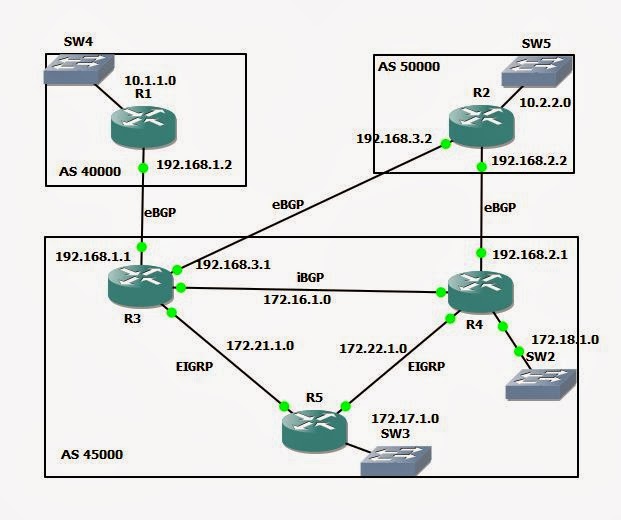
BGP with EIGRP


VLAN

VLAN- Virtual Local Area Network

Why we need VLAN--

I am working for a organization a Network Engineer. And I have to provide a connection to all the employee. So what's the big deal. Take a switch and connect all the users right.

Ya that's right but now I want more thing in this network like I want manager can access internet other employee can't and so many things also like this.

So VLAN is used it to create Virtual LAN's and feel like every one have his personal LAN.By default all the ports of Switch are in vlan-1. And by default there are 5 vlan's on switch.

i)1
ii)1002
iii)1003
iv)1004
v)1005

(use show vlan cmd to see this.)

Now if we want to make some more vlan according to my needs. So here are the configuration.

First is old one but useful some time

S#vlan database
S(vlan)#vlan 50 name my

These two command will create a vlan-50 which name is my. But there is a warning also

"% Warning: It is recommended to configure VLAN from config mode, as VLAN database mode is being deprecated. Please consult user documentation for configuring VTP/VLAN in config mode."


So I'll recommend you to create vlan from Config Mode.

S(config)#vlan 50
S(config-vlan)#name my

"Note- Name is optional, for easiness I always give"

These two command will create vlan 50 which name is my. So see your vlan use 'show vlan'.

Now vlan is created but still we have all the ports in Vlan-1. So time to make member of vlan.

Now we have 2 option either we go to each port and make it member of vlan or we can select a range of ports and make them member of vlan.

So first we'll go to a port

  S(config)#interface fastEthernet 0/1
  S(config-if)#switchport access vlan 50

"Here we are making  f0/1 to member of vlan-50" 

Now i'll select a range.
  S(config)#interface range fastEthernet 0/2 - 0/10
  S(config-if-range)#switchport access vlan 50

"Here we are making f0/2 to f0/10 member of vlan-50"


So by this way we can create multiple vlan and assign port to vlan.
We can't assign a port in multiple vlans. 

Benifites-

1.Security- Mamber of 2 different can't access without admin permission.
2.Traffic Reduce-By default switch broadcast traffic on whole ports of same VLAN so by creating VLAN you can reduce them.

VLANs    |  Range  |    Usages                |  Propogate by VTP
         |         |                          | 
0, 4095  |Reserved | For system use only you     |        -
         |         | can't use or see these     |
         |         | vlans.                   |
__________________________________________________________________
   
 1       | Normal  | Cisco default, you can   |       Yes   
         |         |use the VLAN but can't    |
         |         |modify.                   |
__________________________________________________________________

2- 1001  |Normal   |For Ethernet VLANs,You can|      Yes
         |         |create,use and delete them|
_________________________________________________________________   
1002-    | Normal  |Cisco default for FDDI and|       Yes
1005     |         |Token Ring. You can't     |
         |         | these VLANs              |
_________________________________________________________________

1006-    | Extended|For Ethernet VLAN's only  | No
4096
__________________________________________________________________


Thursday, 21 November 2013

Basic HSRP step by step configuration in GNS 3

We can configure HSRP in GNS 3---

-> HSRP is CISCO Proprietary.
-> Default Hello Timer is 3 Sec.
-> Default Hold Timer is- 10 Sec
-> Default Priority is - 100 


1. In this topology I am using 2 router (R1 and R2) only. R3 is here virtual router.
2. I took 3700 router because Multilayer Switch is not working here so I'll take a Router and install a module in in. (Module- NM-16ESW).
3. I am using my own PC as a HOST (By creating loop back connection).
4.When connecting routers remember you have to do a manual connection and have to connect interfaces of Module which you have installed in routers.Because I am using my router as a switch or can say multilayer switch.

All set start your topology and open console of both routers.

R1--->

R1# vlan database
R1(vlan)#vlan 50 name hsrp
(It's a old process. we can create vlan from config mode. But that's not working in my GNS)

R1(config)#int vlan 50
                #ip address 192.168.1.2 255.255.255.0
                #standby 1 ip 192.168.1.1
                #standby 1 priority 150
                #standby 1 preempt  

"In this configuration we are providing ip to vlan interface because we can't assign ip on switch interface and we are using switch interface"
"standy 1- here 1 is group no of HSRP"
"By default priority is 100. But if we want to give a priority to a router we can increase priority "
"Preempt is used because if R1 is activated and R2 activated after R1, and R2 have priority more than R1, but still R2 not able to become Activated so we start Preempt, after that R2 will coop and become Activated "
R1(conf)#int range f 1/0 - 1
             #switchport mode access
             #switchport access vlan 50
             # no sh

Same configuration will be repeated on R2 except vlan ip address

R2(conf)#int vlan 50
             #ip add 192.168.1.3 255.255.255.0

and don't use Priority command  (using default priority-100)

 After few sec. u'll get a message on R1 that HSRP is enabled and Rouetr is Active.
You can see the status on both router with help of  "show standby" command.


Wednesday, 20 November 2013

Redudancy and Load balancing In Network

In real time scenario every organization wants redundancy  and Load balancing. So today I am going to write on this topic.

First question arise in our mind what is  Redundancy and Load Balancing and why we need it.

With the help of Redundancy  we can create backup connection. For eg. in my organization I have a BSNL connection and for Backup I have Airtel Connection.  Because I have to support my client 24*7 and I can't believe on a  single ISP. So I have a backup connection. But what if I have lost a connection and doing some serious work. Should I run to another router to create connection, not a good idea because I take time to create a physical connection.

Another one is I have connected with both router at a time but now problem is that we have to give a default gate way in our PC when using Internet so which address should I give. And when this Default Gateway goes down I have to change my PC settings.

So finally we want a connection where we can connect both router  at a time and when I when one router goes down my backup router work automatically.

And with this process we can create Redundancy in our Network.


Now question arise that what is LOAD BALANCING. We are using both router and we have to pay to both ISP. Whether  we are using it or not. So I have one more idea can I use both router at a time and when my one router goes down another will take all load. Ya it's good idea I think.


So we have 3 protocol which are used for Redundancy  and Load Balancing.
1.HSRP (Hot Standby Router Protocol)
2.VRRP (Virtual Router Redundancy Protocol)
3.GLBP (Gateway Load Balancing Protocol)

Both 1 and 2 are use only for Redundancy and 3 rd one is used for both Redundancy and Load Balancing.

I'll write about them also...

Thanks for Reading... ---Himanshu Saxena