Tuesday, 26 November 2013

Timed Based ACL

ACL- Access Control List with is used to control  unauthenticated access with help of a list. Normally applied on routers. 

Timed Based ACL- ACL which work on a particular time like I am a network admin in a company and company doesn't provide internet access on weekends or after office hours then timed access list is used.
so we can say that "Timed based ACL permit/Deny traffic for a time/day period"

Example---

Here I have a simplest topology 3 router R1, R2 and R3.But R3 is working as a PC and R2 is working as destination.On R2 we will apply ACL.I will use ACL to permit ping for a time period.
 1. Connect all routers and give ip to interfaces.

 2.We want R3 to work as a pc so
    R3(config)#no ip routing

3.Time to create ACL but  first first we have to create timed access list.No we have two option
  (i).Absolute-- For a particular time period "<start time date> <end time date>"
  (ii)Periodic---For a day period "<day-of -the-week> hh:mm to <day-of-the-week> hh:mm"
      While we using periodic we have multiple option-
       A) daily- Mon to Sun
       B)Weekend-Sat and Sun
       C)Weekday-Mon to Fri
4.Now create a extended ACL and apply it on interface.

R1(config)#time-range permit-ping
                    absolute start 13:00 26 Nov 2013 end 14:26  Nov 2013

R1(config)#access-list 120 permit icmp any any time-range permit-ping

R1(config)#int f 0/0
                  ip access-group 120 in

After applying this ACL I am able to ping R2 from R3 from 1:00 PM to 2:00 PM on 26 Nov 2013.
"Note- you can see currant status of ACL by show acces-list"




Saturday, 23 November 2013

BGP with EIGRP


VLAN

VLAN- Virtual Local Area Network

Why we need VLAN--

I am working for a organization a Network Engineer. And I have to provide a connection to all the employee. So what's the big deal. Take a switch and connect all the users right.

Ya that's right but now I want more thing in this network like I want manager can access internet other employee can't and so many things also like this.

So VLAN is used it to create Virtual LAN's and feel like every one have his personal LAN.By default all the ports of Switch are in vlan-1. And by default there are 5 vlan's on switch.

i)1
ii)1002
iii)1003
iv)1004
v)1005

(use show vlan cmd to see this.)

Now if we want to make some more vlan according to my needs. So here are the configuration.

First is old one but useful some time

S#vlan database
S(vlan)#vlan 50 name my

These two command will create a vlan-50 which name is my. But there is a warning also

"% Warning: It is recommended to configure VLAN from config mode, as VLAN database mode is being deprecated. Please consult user documentation for configuring VTP/VLAN in config mode."


So I'll recommend you to create vlan from Config Mode.

S(config)#vlan 50
S(config-vlan)#name my

"Note- Name is optional, for easiness I always give"

These two command will create vlan 50 which name is my. So see your vlan use 'show vlan'.

Now vlan is created but still we have all the ports in Vlan-1. So time to make member of vlan.

Now we have 2 option either we go to each port and make it member of vlan or we can select a range of ports and make them member of vlan.

So first we'll go to a port

  S(config)#interface fastEthernet 0/1
  S(config-if)#switchport access vlan 50

"Here we are making  f0/1 to member of vlan-50" 

Now i'll select a range.
  S(config)#interface range fastEthernet 0/2 - 0/10
  S(config-if-range)#switchport access vlan 50

"Here we are making f0/2 to f0/10 member of vlan-50"


So by this way we can create multiple vlan and assign port to vlan.
We can't assign a port in multiple vlans. 

Benifites-

1.Security- Mamber of 2 different can't access without admin permission.
2.Traffic Reduce-By default switch broadcast traffic on whole ports of same VLAN so by creating VLAN you can reduce them.

VLANs    |  Range  |    Usages                |  Propogate by VTP
         |         |                          | 
0, 4095  |Reserved | For system use only you     |        -
         |         | can't use or see these     |
         |         | vlans.                   |
__________________________________________________________________
   
 1       | Normal  | Cisco default, you can   |       Yes   
         |         |use the VLAN but can't    |
         |         |modify.                   |
__________________________________________________________________

2- 1001  |Normal   |For Ethernet VLANs,You can|      Yes
         |         |create,use and delete them|
_________________________________________________________________   
1002-    | Normal  |Cisco default for FDDI and|       Yes
1005     |         |Token Ring. You can't     |
         |         | these VLANs              |
_________________________________________________________________

1006-    | Extended|For Ethernet VLAN's only  | No
4096
__________________________________________________________________


Thursday, 21 November 2013

Basic HSRP step by step configuration in GNS 3

We can configure HSRP in GNS 3---

-> HSRP is CISCO Proprietary.
-> Default Hello Timer is 3 Sec.
-> Default Hold Timer is- 10 Sec
-> Default Priority is - 100 


1. In this topology I am using 2 router (R1 and R2) only. R3 is here virtual router.
2. I took 3700 router because Multilayer Switch is not working here so I'll take a Router and install a module in in. (Module- NM-16ESW).
3. I am using my own PC as a HOST (By creating loop back connection).
4.When connecting routers remember you have to do a manual connection and have to connect interfaces of Module which you have installed in routers.Because I am using my router as a switch or can say multilayer switch.

All set start your topology and open console of both routers.

R1--->

R1# vlan database
R1(vlan)#vlan 50 name hsrp
(It's a old process. we can create vlan from config mode. But that's not working in my GNS)

R1(config)#int vlan 50
                #ip address 192.168.1.2 255.255.255.0
                #standby 1 ip 192.168.1.1
                #standby 1 priority 150
                #standby 1 preempt  

"In this configuration we are providing ip to vlan interface because we can't assign ip on switch interface and we are using switch interface"
"standy 1- here 1 is group no of HSRP"
"By default priority is 100. But if we want to give a priority to a router we can increase priority "
"Preempt is used because if R1 is activated and R2 activated after R1, and R2 have priority more than R1, but still R2 not able to become Activated so we start Preempt, after that R2 will coop and become Activated "
R1(conf)#int range f 1/0 - 1
             #switchport mode access
             #switchport access vlan 50
             # no sh

Same configuration will be repeated on R2 except vlan ip address

R2(conf)#int vlan 50
             #ip add 192.168.1.3 255.255.255.0

and don't use Priority command  (using default priority-100)

 After few sec. u'll get a message on R1 that HSRP is enabled and Rouetr is Active.
You can see the status on both router with help of  "show standby" command.


Wednesday, 20 November 2013

Redudancy and Load balancing In Network

In real time scenario every organization wants redundancy  and Load balancing. So today I am going to write on this topic.

First question arise in our mind what is  Redundancy and Load Balancing and why we need it.

With the help of Redundancy  we can create backup connection. For eg. in my organization I have a BSNL connection and for Backup I have Airtel Connection.  Because I have to support my client 24*7 and I can't believe on a  single ISP. So I have a backup connection. But what if I have lost a connection and doing some serious work. Should I run to another router to create connection, not a good idea because I take time to create a physical connection.

Another one is I have connected with both router at a time but now problem is that we have to give a default gate way in our PC when using Internet so which address should I give. And when this Default Gateway goes down I have to change my PC settings.

So finally we want a connection where we can connect both router  at a time and when I when one router goes down my backup router work automatically.

And with this process we can create Redundancy in our Network.


Now question arise that what is LOAD BALANCING. We are using both router and we have to pay to both ISP. Whether  we are using it or not. So I have one more idea can I use both router at a time and when my one router goes down another will take all load. Ya it's good idea I think.


So we have 3 protocol which are used for Redundancy  and Load Balancing.
1.HSRP (Hot Standby Router Protocol)
2.VRRP (Virtual Router Redundancy Protocol)
3.GLBP (Gateway Load Balancing Protocol)

Both 1 and 2 are use only for Redundancy and 3 rd one is used for both Redundancy and Load Balancing.

I'll write about them also...

Thanks for Reading... ---Himanshu Saxena

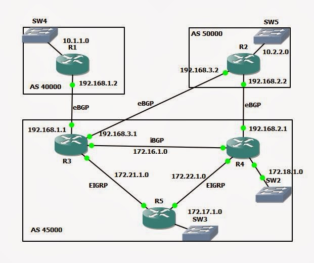
Configuration of BGP

Before moving to BGP configuration first you have to understand its working, terminology, attributes how does it works...
So in this chapter I am going to write BGP Terminology.

1. BGP Terminology-

Main Terms which used in BGP are-
a) BGP Peers
b)Autonomous System (AS)
c)IANA & RIRs
d)NLRI
e)BGP Types
f)BGP Attributes

a) BGP Peers and Peering -

     * BGP Neighbors are called BGP Peers and when BGP Routers exchange routes with another BGP speaking device called BGP Peering.
    * Neighbours established by manual configuration.

b) Autonomous Syastem (AS)-

     * Group of routers that share similar routing policies & operate within a single administrative  domain, typically belongs to one organization can be between 1 to 65,535.

c) IANA and RIRs - 

    * IANA- Internet Assigned Number Authority -( work to manage IP address and AS no.)
    * RIR - Regional Internet Registries -(IANA use RIRs to distribute IP and AS no, there are 5 RIRs across the world)

d) NLRI-

   * Network Layer Reachability Information - By using this we can reach to other network.

e) BGP Types- 

    1.iBGP (Internal BGP)--- Neighbors that belongs to same AS and need not to connected directly.
    2.eBGP(External BGP)--- Neighbors that belongs to different AS and must connected directly.

f) BGP Attributes-

The metrics used by BGP are called path attributes.

    1.AS Path
    2.Next Hop
    3.Local Preference etc... 


2.BGP Message Type-- 


BGP use 4 message type for its functioning. ie whenever a BGP Speaking Router wants to communicate with other BGP speaking Router then Routers use these 4 messages...

a)Open
b)Update
c)Keepalive
d)Notification


a)open-  

     After TCp connection has been established (Note- BGP use port no-179 of TCP for working) open message is sent. This OPEN message contains set of parameters (eg- MD5 password). And before establishing full BGP adjacency neighbor router have to be agreed on these parameters.

b)Update-

     If open message is sent and both routers are agreed on parameters then update message is sent.
     It contains the actual route updates.
     Update Message is composed of
        (i)NLRI
        (ii) AS-Path
        (iii) AS-Path Attributes.

c)Keep-alive Message-

     If routers are not sending information then they can have information about their neighbor with help of Keepalive Message.Keepalive message keep the session running when there is no updates. If a router don't get keepalive message then router remove all paths header from that router which not sending keepalive message.


d)Notification Message-   

     Notification message is used to send error message. For eg update recived is corrupt or router needs to turn down the session unexpectedly. 


3.BGP States-

We can understand BGP state by this FSM (Finite State Machine)--


i)Idle -
       - Not accepting incoming BGP connection.
       - Start a TCP connection with BGP peer.
       - Listens for TCP connection from peer.

ii)Connect -
      - Listens for a TCP connection from peer.
      - If connection is successful then send open message and goto "OPEN SENT".
      - If unsuccessful then go to "ACTIVE".

iii)Active -
      - Unable to establish TCP session.
      - Restart another TCP session with the peer "IDLE".

iv)Open Sent -
      -Listen for an open message from it's peer.
      -Router check the validity of the open message like "BGP Version, MD5 password".
      - If any error occur then sends a notification message to the peer and Indicate why error occured.
      -If there is no error then send Keep alive  message, various timers are set and state is changed to                      "Open Confirmed"

v)Open Confirmed -
     - Peer is listening for a keep alive message.

vi)Established -
    - Peers are send update message.
    - Exchange information about each route being advertised to BGP Peer.


BGP (Border Gateway Protocol)

Border Gateway Protocol (BGP) is a standardized exterior gateway protocol designed to exchange routing and reachability information between autonomous systems (AS).[1] The protocol is often classified as a path vector protocol but is sometimes also classed as a distance vector routing protocol. The Border Gateway Protocol does not involve traditional Interior Gateway Protocol (IGP) metrics, but makes routing decisions based on path, network policies and/or rule-sets configured by a network administrator. The Border Gateway Protocol plays a key role in the overall operation of the Internet and is involved in making core routing decisions.
The Border Gateway Protocol is the successor to the Exterior Gateway Protocol (EGP) and is currently the most widely used exterior gateway protocol by Internet service providers because BGP allows for fully decentralised routing. BGP was originally designed to help transition from the core ARPAnet model to a decentralized system that included the NSFNET backbone and its associated regional networks.


1.Current Version

The current version of BGP is version 4 (BGP4) codified in RFC 4271.

2.Uses

Most Internet service providers must use BGP to establish routing between one another (especially if they are multihomed). Therefore, even though most Internet users do not use it directly, BGP is one of the most important protocols of the Internet.Compare this with Signaling System 7 (SS7), which is the inter-provider core call setup protocol on the PSTN
Very large private IP networks use BGP internally. An example would be the joining of a number of large OSPF (Open Shortest Path First) networks where OSPF by itself would not scale to size. Another reason to use BGP is multihoming a network for better redundancy, either to multiple access points of a single ISP (RFC 1998) or to multiple ISPs.

Tuesday, 19 November 2013

Cisco ASA on GNS 3

There are so many version of GNS 3 on internet. Latest one is 8.6 but I use 8.3 but it's a stable version, and I suggest you to use the same.

Today we are going to learn how we can configure ASA on GNS 3.

1. Download ASA 8.4 file from internet. (I suggest to download it from 4 Shared.com).

2.Open your GNS -> Edit -> Preference -> Qemu ->  ASA.

3. Copy and pest these two command as it is...

Qemu Options: -vnc none -vga none -m 1024 -icount auto -hdachs 980,16,32
Kernel cmd line: -append ide_generic.probe_mask=0x01 ide_core.chs=0.0:980,16,32 auto nousb console=ttyS0,9600 bigphysarea=65536
4. Brows Initrd: and Kernal: file and apply + save.
I have seen on so many site that how we can use multiple ASA in GNS 3 at a time.

Best result (Not working by me but you try at least once.)
 
"If you want to run two ASAs, you will have to change the Qemu options on the second firewall as below Qemu Options: -vnc :2 none -vga none -m 1024 -icount auto -hdachs 980,16,32"
 

Looking at Packets


Cisco Networking: Looking at Packets

Data containers are dubbed frames in the data link layer (Layer 2) and packets in the network layer (Layer 3). In the network layer, you look only at the section of the frame that was referred to as data in the Ethernet frame. As the Ethernet frame moves up from the data link layer to the network layer, the data link header is removed.
Removing the data link information removes destination and source address fields (which store the MAC addresses of the network devices), and the type field.
Because the preamble and FCS information was removed when the Ethernet frame was sent from the physical layer to the data link layer, this now leaves just the data. The data is not just a blob though. At the network layer, this information is referred to as a packet, and it has its own address data and fields; but when you look at it from the Ethernet frame level, you do not care what that data is.

Looking at packets

After you strip off the Ethernet or data link layer structures, you look at what the data link layer considered to be data, which is a packet. The packet’s structure will be based on the network layer protocol, it is reasonable to call the packet an IP packet.
Just like the Ethernet frame had an Ethernet header and a data section, the IP packet has an IP header and a data section. The following figure shows the contents of an IP packet contained within the Ethernet frame. Notice that the entire IP packet is found in the data field.

Viewing packet structure

The IP packet is defined by its header, and that header contains many fields. The key elements that are in the header are
• Version: This is used to identify the IP version being used. There are really only two choices, either version 4 (the first production version of IP that was implemented), or version 6 (which is currently in the process of being implemented over the Internet). The example shows the IPv4 header here because it is likely the one you will encounter most over the next decade.
• Time to Live (TTL): The length of time this packet can remain on the network. Each router that handles this packet decrements (reduces) this counter by at least one.
• Protocol: The transport layer protocol where the data portion of the IP packet is to be delivered. This will be either Transmission Control Protocol (TCP) or User Datagram Protocol (UDP).
• Header checksum: The header checksum data that the verification calculation is based on is only the header data, and the result of that calculation is stored in the header checksum field. If the header is intact, IP considers the packet good.
• Source address: The IP address of the device that sends the packet onto the network. This is also where any network-level error messages are sent, including Internet Control Message Protocol (ICMP) delivery failures or control messages.
• Destination address: The address the packet is sent to.
• Data: As with the Ethernet frame, the data portion is sent to the transport layer, to either the TCP or UDP. IP does not care what is found here; it is merely the delivery means.

Monday, 18 November 2013

What is Network

What is Network

In general way network is the connection between two or more things.

(1.) In Term Of Computer--

A network consists of two or more computers that are linked in order to share resources (such as printers and CDs), exchange files, or allow electronic communications.

Basic concept of Networking


Goal:
It is very necessary to fix the goal before starting any task.  Here we are going to understand the concepts of networking. So, our goal must be to cover all the parts of networking through this we can understand each and every concept related to networking in easy way. Our Primary goal is to convey the concepts of networking and understating of whole network that What and why it is? And how it works?
After completing this unit you will be very comfortable with:                
    1.What is network 
    2.How computer network work    
    3.Network configuration   
    4.IP address concepts
    5.Network topology
    6.Network devices
    7.Network setup using commands
    8.Some network monitoring tools. 
    9.Client server model

Friday, 15 November 2013

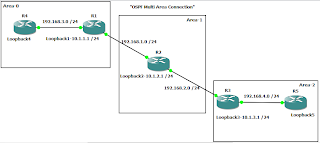
OSPF Multi Area Connection

Yes i am right. It is possible to connect multiple area  in OSPF Topology without connecting Area-0. In this case we have to create virtual links between Area-0 and Area-2 and Area-1 will behave like a medium.

Tuesday, 5 November 2013

Cisco IOS Policy-Based Routing


How to use the Cisco IOS Policy-Based Routing Features?

The use of a dynamic routing protocol on a company's WAN and LAN is standard practice today. Whether you use OSPF or EIGRP to automatically determine the
path that your traffic takes, at some point, for some reason, you may want to direct that traffic for yourself. In this article, we will learn what
Policy-based routing is, how it can help you, and what a basic configuration looks like.

What is Policy-based Routing?

With policy-based routing (which we will call PBR from here on out), you get the option to implement policies that selectively cause packets to take
different paths. Additionally, PBR can mark packets so that certain types of traffic get prioritized. One example of PBR is, say that your OSPF routing
protocol says that a packet with a destination of 10.1.1.1 should go out interface e0/0, you could create a policy so that packets destined to 10.1.1.1,
instead, go out interface e1/0. Or, you could make this happen ONLY when the source of that packet was 192.168.1.1.

How does policy based routing work?

If you look at the Cisco IOS Order of Operations, Policy routing always happens BEFORE regular routing. What policy routing does is to inspect the traffic
 on the interface where the policy is applied and then, based on the policy, make some decision. First, the traffic has to be identified "matched" according
 to the policy. Second, for each match, there is something "set". What is set could be that the traffic matches must exit out a different interface, or the
traffic could be given a higher priority, or it could choose to just drop that traffic.
The "matching" of the traffic is usually done with an ACL (access-control list) that is referenced by a route-map. In the route-map, there is a "match" for
 the traffic defined in that ACL then a "set" for that traffic where the network administrator defines what he or she wants to happen to that traffic
 (prioritize it, route it differently, drop it, or other actions). Policies can be based on IP address, port numbers, protocols, or size of packets.

How to apply policy-based routing

Let's look at an example of how we could use PBR. Say that we wanted to find any traffic that is destined for IP device 10.1.1.1 and, instead of sending it
 wherever the routing protocol says it should go, we are going to send it out interface Fa3/0.

To do this, here are the steps we would take:

Step 1 - define an ACL

Keep in mind that whatever is permitted by this ACL is what will be matched. You don't want to permit everything. Usually, I take advantage of the implicit
deny at the bottom of the ACL and just create an ACL that permits what I am going to take action on in the route-map.
So, just create a simple ACL:
Router(config) # access-list 101 permit ip any host 10.1.1.1
This ACL permits only traffic with a destination IP of 10.1.1.1 (the traffic we want to send elsewhere)

Step 2 - create a route-map

To create a route-map, go into route-map configuration mode, like this:
Router(config) # route-map reroute10traffic permit 10
Router(config-route-map) #
Next, set your match policy to match the traffic in ACL 101, like this:
Router(config-route-map) # match ip address 101
This will match all the traffic permitted through ACL 101.
Next, you need to set some action on that traffic. What do you want to happen to that traffic? Let's tell the router to send it out interface Fast Ethernet
3/0, like this:
Router(config-route-map) # set interface Fa3/0

Step 3 - Apply the route-map to the interface

Next, you need to apply this policy/route-map to the interface where the traffic is coming in.
Router(config) # interface Fast Ethernet 3/0
Router(config-if) # ip policy route-map reroute10traffic
According to the official Cisco Policy Routing documentation, "One interface can have a only one route map policy applied.tag; but you can have several
route map entries, each with its own sequence number. Entries are evaluated in order of their sequence numbers until the first match occurs. If no match
occurs, packets are routed as usual."
Now exit and you are done!
You can view your route-maps with show route-map.